|
PATH |
The FireWire connector has six contacts, as shown in Figure 3-3. The connector pin assignments are shown in Table 3-3.
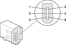
Table 3-3 FireWire connector pin assignments
The power pin provides a maximum voltage of 24 V (no load) and up to 15 W total power on both connectors. When the computer is off, the power pin accepts external power at 8 to 33 V, in conformity with the P1394a draft standard.
Pin 2 of the 6-pin FireWire connector is ground for both power and inner cable shield. If a 4-pin connector is used on the other end of the FireWire cable, its shell should be connected to the wire from pin 2.
The signal pairs are crossed in the cable itself so that pins 5 and 6 at one end of the cable connect with pins 3 and 4 at the other end. When transmitting, pins 3 and 4 carry data and pins 5 and 6 carry clock; when receiving, the reverse is true.
For additional information about the FireWire interface and the Apple APIs for FireWire device control, refer to the resources available on the Apple FireWire Web site at
http://developer.apple.com/hardware/FireWire/


