Input and Output Devices
This chapter describes the Power Mac G5 computer’s built-in I/O devices and the ports for connecting external I/O devices. Each of the following sections describes an I/O port or device.
In this section:
USB Ports
FireWire Ports
Ethernet Port
Disk Drives
Internal Modem
AirPort Extreme Card
Bluetooth Technology
Keyboard
Mouse
Audio
Video Monitor Ports
Dual Display Extended and Mirror Modes
USB Ports
The Power Mac G5 computer has two external Universal Serial Bus (USB) 2.0 ports on the back and one on the front of the enclosure and an internal connection to the AGP slot for the Apple display. The external USB ports are off of the USB controller connected to the PCI bus, bridged by K2. In addition, there are two USB 1.1 ports on the keyboard. The USB ports are used for connecting the keyboard and mouse as well as additional I/O devices such as printers, scanners, and storage devices.
All USB ports are fully compliant with the USB 2.0 specification, including support for high-speed (480 Mbps) devices using an Enhanced Host Controller Interface (EHCI). Ports are automatically routed to a companion OHCI controller when a classic-speed (full-speed or low-speed) USB device is attached to a root hub port.
Each USB rear port is connected to a separate USB root hub in classic speeds, allowing the USB ports to support 12 Mbps devices at the same time with no degradation of their performance. The USB root hubs are also connected to the internal USB modem and to the USB port on the ADC monitor connector.
The three external USB ports and the port supporting the Apple display comply with the Universal Serial Bus Specification 2.0. The two ports on the keyboard comply with the Universal Serial Bus Specification 1.1 Final Draft Revision. For low-speed and full-speed devices, the USB register set complies with the Open Host Controller Interface (OHCI) specification. For high-speed devices, the USB register set complies with the Enhanced Host Controller Interface (EHCI) specification.
For more information about USB on Macintosh computers, please refer to Apple Computer’s Accessing Hardware from Applications and the other sources listed in “USB Interface.”
USB Connectors
The USB ports use USB Type A connectors, which have four pins each. Two of the pins are used for power and two for data. Figure 3-1 shows the connector and Table 3-1 shows the signals and pin assignments.

Pin | Signal name | Description |
|---|---|---|
1 | VCC | +5 VDC |
2 | D– | Data – |
3 | D+ | Data + |
4 | GND | Ground |
The Power Mac G5 computer provides 5 V power for the USB ports and up to 500 mA on each port. The power is provided in both run and sleep mode. The ports share the same power supply; a short circuit on one disables all ports until the short has been removed.
The USB ports support all USB 2.0 speeds: high-speed (480 Mbps) and classic USB speeds of full-speed (12 Mbps) and low-speed (1.5 Mbps). High-speed operation requires the use of shielded cables.
The Macintosh system software supports all four data transfer types defined in the USB specification, as well as split transactions for classic-speed devices attached to high-speed hubs.
Waking Up From Sleep
As defined in the USB-suspend mode of the USB specification, USB devices can provide a remote wakeup function for the computer (resume signalling). The USB root hub in the computer is set to support remote wakeup whenever a device is attached to the bus. The device wakes the computer by sending a RESUME event to the USB root hub. The mouse and keyboard that come with the computer use this method to wake the computer on a key press or mouse click.
FireWire Ports
The Power Mac G5 computer has one FireWire 800 port based on IEEE 1394b and two FireWire 400 IEEE 1394a ports. Each FireWire port
supports booting the system from a mass storage device
supports target disk mode
provides bus repeating capability as long as the computer is connected to AC power
provides power for FireWire devices both in run and sleep mode (useful for charging the iPod)
The three FireWire ports share a single power supply that can provide up to 15 watts total. The three ports are all on the same FireWire bus and can connect to up 62 other FireWire devices.
The FireWire hardware and software provided with the Power Mac G5 computer are capable of all asynchronous and isochronous transfers defined by IEEE standards 1394a and 1394b.
Note: FireWire cables are not included with this product and must be purchased independently, if required.
For more information about FireWire on Macintosh computers, please refer to the Apple FireWire website and the other sources listed in “FireWire Interface.”
FireWire 800 Connector
The FireWire 800 port on the Power Mac G5 computer is based on IEEE 1394b and enables a 800 Mbps transfer rate. FireWire 800 uses a 9-pin connector and is backwards compatible with original 1394a (FireWire 400) devices with 6-pin or 4-pin connectors. With the appropriate cable, the 9-pin port works seamlessly with legacy FireWire devices. Cables are available to go from both 6-pin and 4-pin connectors to a 9-pin, and 9-pin to 9-pin.
The 9-pin FireWire 800 connector is shown in Figure 3-2. Its connector signals and pin assignments are shown in Table 3-2.
VP (pin 8) provides up to 15 W power, shared with the other FireWire connectors. The voltage on the power pin is approximately 25 V.
The 9-pin FireWire port is capable of operating at 100, 200, 400, and 800 Mbps, depending on the device it is connected to. Using a cable with a 9-pin connector at one end and a 4-pin or 6-pin connector at the other, the 9-pin port is capable of directly connecting to all existing FireWire devices. Using a cable with 9-pin connectors at both ends, the 9-pin port is capable of operating at 800 Mbps.
The IEEE 1394b standard defines long-haul media using Cat 5 UTP and several kinds of optical fiber. The Power Mac G5 computer is interoperable with such cables but cannot be directly connected to them. To use long-haul cables, connect the computer to a 1394b hub that has the desired kind of long-haul connectors. If the hub has a bilingual port, that port can be connected to any of the computer’s FireWire ports. If the hub has a beta-only port, it can be connected only to the computer’s 9-pin port.
FireWire 400 Connector
The FireWire 400 ports 1 and 2 use the six-pin connectors shown in Figure 3-3. The connector signals and pin assignments are shown in Table 3-3.
The power pin provides up to 15 W total power, shared with the other FireWire connectors. The voltage on the power pin is approximately 25 V.
Pin 2 of the 6-pin FireWire connector is ground return for both power and the inner cable shield. In a FireWire cable with a 4-pin connector on the other end, the wire from pin 2 is connected to the shell of the 4-pin connector.
The signal pairs are crossed in the cable itself so that pins 5 and 6 at one end of the cable connect with pins 3 and 4 at the other end. When transmitting, pins 3 and 4 carry data and pins 5 and 6 carry clock; when receiving, the reverse is true.
FireWire Device Programming
Mac OS X includes general support for the FireWire bus and specific support for various kinds of FireWire devices and protocols. Developers can use the built-in support or provide additional applications and drivers for use with their products.
The general FireWire services will configure the FireWire bus, scan the bus for new devices, and allow multiple drivers and devices to share a single FireWire interface cooperatively. The general services also publish information about the bus and the devices in the IO Registry, so that IO Kit can match protocols and drivers to each connected FireWire device.
The specific device and protocol support in Mac OS X as provided with the Power Mac G5 includes the following:
General services for Serial Bus Protocol 2 (SBP-2) and support for most mass storage devices using SBP-2, such as hard disk drives, optical drives, flash card readers, Target Disk Mode (see “Target Disk Mode,” and the iPod. Mac OS X can boot from most of these devices.
General services for the Audio Video Control (AV/C) protocol and support for most digital video (DV) cameras and decks using this protocol, including video capture through standard QuickTime APIs.
A QuickTime device driver for IIDC/DCAM type cameras such as the iSight.
A network device driver supporting IP (Internet Protocol) over FireWire according to IEEE RFC 2734.
Additional services for user-space and kernel access to all FireWire resources.
For information on writing FireWire drivers or applications, download the latest FireWire SDK from http://developer.apple.com/sdk/
Booting from a FireWire Device
The Power Mac G5 computer can boot from a FireWire storage device that implements SBP-2 (Serial Bus Protocol) with the RBC (reduced block commands) command set.
For additional information about the FireWire interface and the Apple API for FireWire device control, see the references shown in “FireWire Interface.”
Target Disk Mode
The user has the option at boot time to put the computer into a mode of operation called Target Disk Mode (TDM). When the Power Mac G5 computer is in Target Disk Mode and connected to another Macintosh computer by a FireWire cable, the Power Mac G5 computer operates like a FireWire mass storage device with the SBP-2 (Serial Bus Protocol) standard. Target Disk Mode has two primary uses:
high-speed data transfer between computers
diagnosis and repair of a corrupted internal hard drive
The Power Mac G5 computer can operate in Target Disk Mode as long as the other computer has a 1394a or 1394b FireWire port and either any version of Mac OS X or Mac OS 9 with FireWire software version 2.3.3 or later.
To put the Power Mac G5 computer into Target Disk Mode, restart the computer and hold down the T key until the FireWire icon appears on the display. Then connect a FireWire cable from the Power Mac G5 to the other computer. When the other computer completes the FireWire connection, a hard disk icon appears on its desktop.
If you disconnect the FireWire cable or turn off the Power Mac G5 computer while in Target Disk Mode, an alert appears on the other computer.
To take the Power Mac G5 out of Target Disk Mode, drag the hard disk icon on the other computer to the trash, then press the power button on the Power Mac G5 computer.
Ethernet Port
The Power Mac G5 computer has a built-in Ethernet port that supports 10/100/1000 Mbps transfer rates. In operation, the actual speed of the link is auto-negotiated between the Ethernet PHY device that is internal to the K2 IC and the bridge, router, hub, switch, or other Mac or PC to which it is connected. The Ethernet port is auto-sensing and self-configuring to allow connection via either a cross-over or straight-through cable.
Both CAT 5 unshielded twisted pair (UTP) and shielded twisted pair (STP) cables work with the Ethernet port. An STP cable is recommended for noisy environments or run of greater than 100 meters.
Note: When connecting a Power Mac G5 computer directly to another computer without using an Ethernet hub, a crossover cable is not required; circuits in the PHY detect the type of connection and switch the signal configuration as required.
The connector for the Ethernet port is an RJ-45 connector on the back of the computer. Table 3-4 shows the signals and pin assignments for 10Base-T/UTP and 100Base-TX operation. Table 3-5 shows the signals and pin assignments for 1000Base-TX operation.
To interconnect two computers for 1000Base-TX operation, you must use 4-pair cable (Category 5 or 6).
The Ethernet interface in the Power Mac G5 computer conforms to the ISO/IEC 802.3 specification, where applicable, and complies with IEEE specifications 802.3i (10Base-T/UTP), 802.3u-1995 (100Base-TX), and 802.3ab (1000Base-TX).
Disk Drives
The Power Mac G5 computer has one 5.25 inch bay for optical drive access through the front panel and two 3.5 inch bays for internal hard disk drives. The optical drive is connected to the Ultra ATA/100 bus; the factory installed drive runs at 33 MHz. The standard configuration of the Power Mac G5 provides a SuperDrive; a build-to-order Combo drive is available.
Hard Disk Drives
The enclosure has one drive carrier with two 3.5 inch bays for fixed-media mass storage devices. The drive carrier has data and power connectors for the both drives. The two drives on the independent Serial ATA buses implement revision one ports. Hard disk drive capacities are 80 GB and 160 GB with a 250 GB build-to-order option for some configurations. For references to SATA website information, refer to “Serial ATA.”
SCSI Drive
SCSI drives and SCSI PCI controller cards are available from third party providers. The Power Mac G5 computer supports external SCSI drives only.
SuperDrive
The Power Mac G5 computer has a tray-loading SuperDrive (combination DVD-R and CD-RW drive). The SuperDrive can read and write DVD media and CD media, as shown in Table 3-6. The DVD-R/CD-RW drive also provides DVD-Video playback.
The Apple SuperDrive writes to DVD-R 4.7 gigabyte General Use media. These discs are playable in most standard DVD players and computer DVD-ROM drives.
For compatibility information regarding recordable DVD formats, refer to
http://dvddemystified.com/dvdfaq.html#4.3
Digital audio signals from the SuperDrive can be played through the sound outputs under the control of the Sound Manager.
Combo Drive
As a build-to-order option, the Power Mac G5 computer can have a tray-loading combination DVD-ROM and CD-RW drive.
The Combo drive can read DVD media and read and write CD media, as shown in Table 3-7. The DVD-ROM/CD-RW drive also provides DVD-Video playback.
Digital audio signals from the Combo drive can be played through the sound outputs under the control of the Sound Manager.
Internal Modem
The Power Mac G5 computer has an internal modem module. The external I/O connector for the modem is an RJ-11 connector installed on the rear panel of the computer. The modem has the following features:
modem bit rates up to 56 Kbps, supporting V.90 and V.92 modem standards
fax modem bit rates up to 14.4 Kbps
Depending on the configuration, the modem appears to the system as a USB device or I2S device that responds to standard AT commands. The modem provides a sound output for monitoring the progress of the modem connection.
AirPort Extreme Card
The Power Mac G5 computer supports the optional AirPort Extreme Card, an internal wireless LAN module. The AirPort Extreme Card is available as a build-to-order option or as a user-installable upgrade through the Apple Store.
By communicating wirelessly with a base station, the AirPort Extreme Card can be used for Internet access, email access, and file exchange. A base station provides the connection to the Internet or the bridge between the wireless signals and a wired LAN or both. The AirPort Extreme Base Station has connectors for a wired LAN, a DSL or cable modem, and a standard telephone line using the built-in 56 Kbps modem that is available on some base stations.
When the AirPort Extreme option is included in the factory order, an external AirPort Extreme antenna is provided in the accessory kit and must be installed on the AirPort Extreme antenna port on the rear of the enclosure.
Complying with the IEEE 802.11g standard, AirPort Extreme transmits and receives data at rates up to 54 Mbps. Airport Extreme is also compatible with other devices that follow the IEEE 802.11b standard, including PC's. For more information about Wi-Fi and compatibility, see the reference at “Wireless Networks.”
Note: As is the case with the existing IEEE 802.11b standard, actual data throughput will be lower than the indicated maximum connection speeds.
Data Security
AirPort Extreme has several features designed to maintain the security of the user’s data:
The system uses direct-sequence spread-spectrum (DSSS) technology that uses a multibit spreading code that effectively scrambles the data for any receiver that lacks the corresponding code.
The system can use an Access Control List of authentic network client ID values or MAC addresses (Ethernet or AirPort IDs) to verify each client’s identity before granting access to the network.
When communicating with a base station, AirPort Extreme uses up to 128-bit encryption to encode data while it is in transit.
The AirPort Extreme Base Station can be configured to use NAT (Network Address Translation), protecting data from would-be Internet hackers.
The AirPort Extreme Base Station can authenticate users by their unique MAC addresses (AirPort IDs), preventing unauthorized computers from logging into a network. Network administrators can take advantage of RADIUS compatibility, used for authenticating users over a remote server.
As an additional data security measure, VPN can be used in conjunction with the AirPort Extreme data security.
AirPort Extreme Hardware
The AirPort Extreme Card is a wireless LAN module compliant with the IEEE 802.11g standard using both OFDM (orthogonal frequency-division multiplexing) and DSSS technologies. Using DSSS, AirPort Extreme is interoperable with other Wi-Fi certified, PC-compatible wireless LANs that conform to the 802.11b standard at speeds of 11 Mbps, 5.5 Mbps, 2 Mbps, and 1 Mbps. Using OFDM, AirPort Extreme is compatible with all 802.11g standard speeds.
The AirPort Extreme wireless interface is on the PCI bus.
AirPort Extreme Software
Software that is provided with the AirPort Extreme Card includes
AirPort Setup Assistant (located in the Applications/Utilities folder), is an easy-to-use program that guides the user through the steps necessary to set up the AirPort Extreme Card or set up an AirPort Extreme Base Station.
Users can switch between wireless networks and can create and join peer-to-peer networks. These functions are accessed via the AirPort - Menu-Extra pulldown, which is enabled by a checkbox in System Preferences.
AirPort Admin Utility (located in the Applications/Utilities folder), is a utility for advanced users and system administrators. With it the user can edit the administrative and advanced settings needed for some advanced configurations.
Bluetooth Technology
Available as a fully-integrated, build-to-order option, Bluetooth is an open specification that enables short-range wireless connections between desktop and laptop computers and a host of other peripheral devices. Bluetooth support is built into Mac OS X and compliant with Bluetooth specification v1.1. It operates on a globally available 2.4 GHz frequency band (ISM band) for worldwide compatibility and has a maximum throughput of 1Mbps.
The Bluetooth technology supports the following profiles:
synchronization — enables synchronization of devices over Bluetooth
serial — provides a wireless serial connection to other Bluetooth devices
dial-up networking (DUN) — enables a mobile phone to act as a modem
object push — enables the transfer of files between Bluetooth devices
human interface device (HID) — enables the use of Bluetooth input devices (keyboards and mice)
Bluetooth file transfer profile (FTP) — enables browsing of the file system of other Bluetooth devices which support Bluetooth FTP.
hardcopy cable replacement profile (HCRP) — describes how to send rendered data over a Bluetooth link to a device, such as a printer. Although other profiles can be used for printing, the HCRP is specially designed to support hardcopy applications. Note: currently, to use this profile, Apple’s Bluetooth Update Version 1.5 must be installed.
headset profile (HSP) — enables the use of Bluetooth-enabled wireless headsets for applications such as iChat. This profile does not enable use of Apple Speech Recognition due to the fact that it is a low-precision audio channel. Note: currently, to use this profile, Apple’s Bluetooth Update Version 1.5 as well as Firmware Update Version 1.1 must be installed.
synchronous, connection-oriented (SCO) — enables isochronous and voice communication, including most Bluetooth headsets.
Bluetooth is available as a build-to-order option, which is installed by Apple at the time of purchase as a fully integrated module. Accessing the Bluetooth capabilities without purchasing the integrated module will require a third-party dongle.
When the Bluetooth option is included on the factory order, the Bluetooth antenna is provided in the accessory kit and must be installed on the Bluetooth antenna port on the rear of the enclosure.
For more information on Bluetooth technology, refer to “Bluetooth.”
Keyboard
The Power Mac G5 computer comes with an Apple Keyboard. It is a full-size keyboard with function keys and separate numeric keypad and editing sections.
The keyboard has an attached 1-meter cable and comes with a 1-meter extender cable for installations where the computer is located on the floor or away from the immediate desktop area.
Keyboard Features
Here is a list of the features of the Apple Keyboard.
sloped design
109 keys (on the ANSI versions)
16 function keys
6 editing keys (Page Up, Page Down, Home, End, Forward Delete, and Help)
USB HID Consumer Page Usage multimedia control keys
full travel, standard pitch keys on alphanumeric, editing, and keypad sections, including function keys and cursor-position keys
localized worldwide: 33 versions, standard layouts (including: ANSI, JIS, ISO)
LED indicator on the Num Lock key
USB hub functionality with two USB 1.1 sockets
Keyboard Layout
There are localized versions of the Apple Keyboard for use in different parts of the world. The three standards used are ANSI (US and North America), JIS (Japan), and ISO (Europe).
Applications can determine which keyboard is connected by calling the Gestalt Manager and checking for the corresponding value of the gestaltKeyboardType selector.
Figure 3-4 shows the keyboard layout for the ANSI keyboard.
MultiMedia Control Keys
The keyboard has six multimedia keys: Volume Up, Volume Down, Mute, Brightness Up (F15), Brightness Down (F14), and Eject. Theses keys provide direct control of the features on the computer by way of the USB.
Keyboard and USB
The Apple Keyboard is designed to work with the computer by way of the USB ports. The keyboard has a captive cable with a USB Type A connector. The keyboard is a bus-powered USB hub with two USB Type A ports.
Warning: A bus-powered hub as defined in the USB specification does not provide enough power to support a second bus-powered hub. A second bus-powered hub must be connected to a USB port on the computer or other self-powered hub, not to a port on the keyboard.
Apple provides a HID class driver for the Apple Keyboard, which supports the USB boot protocol. Other keyboards intended for use on the Macintosh platform must support the HID boot protocol, as defined in the USB Device Class Definition for Human Interface Devices (HIDs).
Programmer’s Switches
Key combinations for programmer’s switches that used the Power button on earlier models now use the Eject key. Here are the key combinations for the Power Mac G5 computer.
Control-Command-Eject: restart immediately (reset)
Control-Command-Option-Eject: shut down immediately
Control-Eject: display the dialog for shutdown, restart, and sleep
The key combinations are decoded in software and may not be available under some crashed conditions.
NMI without Programmer’s Switch
Current Macintosh computers do not have a programmer’s switch, which allowed users to generate a non-maskable interrupt (NMI). The paragraphs below describe how to generate an NMI from a remote session for systems that do not have a physical programmer's switch.
Starting with Mac OS X 10.1.2, the OS will promote and recognize the DB_NMI bit in the “boot-args” property of the “chosen” node from Open Firmware. When the DB_NMI bit is set, the user can generate a non-maskable interrupt (NMI) by pressing the system's power button. This replaces the power button’s sleep or wake response. The system reads the state of the bit at boot time from the boot-args configuration variable. For more information about the debug flags, please see Inside Mac OS X: Kernel Programming.
To set the DB_NMI bit, enter the following command at the Terminal to display the current debug flag settings.
% nvram boot-args |
Add the parameter debug=0x4, as follows.
% sudo nvram boot-args="<current settings> debug=0x4" |
After rebooting, press the power button for approximately 3 seconds to generate an NMI.
Note: If the power button is pressed for more than five seconds, the system will immediately power off.
The power button will retain this functionality until Mac OS X is restarted without the DB_NMI bit set. To clear this bit, issue the nvram command omitting debug=0x4 parameter, as follows.
% sudo nvram boot-args="" |
Note: The debug flags bit will be cleared if you use System Preferences to change the startup disk. It may also be cleared if you perform an installation that requires a restart.
Mouse
The Power Mac G5 computer comes with an Apple Mouse. The mouse case is made of polycarbonate plastic.
The Apple Mouse uses optical tracking in place of the traditional rolling ball. It works on almost any surface, though nonreflective, opaque surfaces without repetitive patterns work best.
Audio
The Power Mac G5 computer supports a sound system with both digital and analog audio. The new digital capability features Sony/Phillips Digital Interface (S/PDIF) input and output using optical connectors. S/PDIF technology results in a clean audio signal with no added noise to or from an external audio device.
Under the control of the system software, the sound circuitry digitally creates and records sounds. The Power Mac G5 computer can receive input only from either the analog input or the digital input. However, it can output simultaneously to digital and analog devices: the internal speaker, the headphone jack, the audio output jack, and the S/PDIF output connector.
By default, when components are plugged into the headphone jack or the rear line-out, the sound system mutes the internal speaker.
The headphones, rear line-out jack, and S/PDIF output are only muted when selected in the System Preferences. Muting and sound options are set in System Preferences:Sound:Output.
The analog and digital sound circuitries are not independent. Different audio streams cannot be played to the analog and digital circuitry. The selection of digital or analog output is performed through Sound pane in System Preferences.
The sound circuitry and audio device drivers handle audio data in multiple formats. Both digital and analog sound circuitry handle audio input and output data at sample rates of 32.0 kHz, 44.1 kHz, and 48.0 kHz at sample depths of 16 bits and 24 bits.
If audio data sampled from another computer at a lower rate is played as output on the Power Mac G5, the Core Audio (Mac OS X’s OS Level Audio API) transparently up-samples the data to the currently set sampling frequency prior to sending the audio data to the sound circuitry. To maximize audio fidelity, the Core Audio samples are stored as 32-bit floating point. The Sound Manager exists as a Carbon compatibility layer, but developers are encouraged to move their applications to Core Audio for maximum performance and fidelity, because the Sound Manager is capable of representing samples only as 16-bit values.
For more information about audio API’s on Mac OS X, visit the Apple audio technologies developer web page at
http://developer.apple.com/audio/
Optical S/PDIF Audio
Digital data is transmitted to and from the digital audio I/O using optical cables. The physical connectors, commonly referred to as TOSLink, are for both input and output and conform to IEC60874-17. The TOSLink friction-lock type F-05 connectors are available from pro-audio, musician’s supply, hi-fi and other retailers. The 7.5 mm digital optical TOSLink input and output connectors, shown in Figure 3-5, are located on the back of the enclosure.

The digital I/O circuitry can either perform input clock recovery on an incoming data stream or can sample using the internal clock. If samples are clocked using the internal clock, the data is run through the sample-rate converter on the digital circuitry. To enable bit-accurate copies, the external clock should be enabled in Audio MIDI Setup. Developers of applications that need this capability will need to provide access to the input clock recovery control.
Audio signals from the audio input jack are converted to digital data internally. All audio is handled digitally inside the computer, including audio data from the CD or DVD drive and from devices connected to the USB and FireWire ports. Audio data is converted to analog form for output to the internal speaker, the headphones, line output jacks, or external speakers.
For details on the S/PDIF digital input and output electrical specifications, refer to “Digital Optical Input/Output Specifications.”
The Power Mac G5 computer also has the ability to lock its internal audio hardware to the incoming audio stream to synchronize the audio subsystem to an external device supplying the audio stream. This function allows audio and video to play in sync with the external audio or video device. The data format for signals transmitted over the optical cable is S/PDIF protocol IEC 60958-3.
The Power Mac G5 computer’s audio subsystem has built-in sample-rate conversion (SRC) that allows the incoming audio to have a different rate than the playback audio, enabling the audio to come in the digital-in connector. For the best digital input quality in its purest form, set the audio clocking preference to “External Clock.”
External Clocking
When the Power Mac G5 computer is set to “External” clocking, the computer audio circuitry will track and follow the incoming digital sampling rate and lock the internal audio hardware to the sampling rate of the external device. The external clock must be stable enough to be locked onto, otherwise the digital circuit will signal an error and the driver will fall back to using the internal clock.
Internal Clocking
When the Power Mac G5 computer is set for “Internal” clocking, the computer audio circuitry will run using the computer’s internal clock. Incoming digital audio is automatically sample-rate converted to the selected output sample rate using the sample rate converter in the audio chip. The sample rate converter is high quality and does not use CPU bandwidth for audio conversion.
Digital Optical Input/Output Specifications
Based on playback of a 1 kHz, -1dBFS 24-bit sine wave playback, 24-bit 44.1 kHz output sample rate (unless otherwise specified below) the digital sound input and output have the following electrical characteristics (nominal specifications):
Fsi – input sample rates (external clock mode): 32 kHz, 44.1 kHz or 48 kHz
Fsi – input sample rate (internal clock mode): 16 kHz – 96 kHz
bits per sample: 16-bit or 24-bit
SNR (external clock mode): >130 dB
SNR (internal clock mode, 16 kHz < Fsi < 96 kHz): >110 dB
THD+N (external clock mode): < -130 dB (0.00003%)
THD+N (internal clock mode, 16 kHz < Fsi < 96 kHz): < -110 dB (0.0003%)
Audio Line-in
The Power Mac G5 has a stereo audio line-in jack on the back panel. The audio inputs are designed to accept high-level audio signals: 2 Vrms or +8 .2 dbu, which is the standard output level from CD and DVD players. The output level of some consumer audio devices is lower, often 0.316 Vrms or –10 dbV. Sound recordings made on the Power Mac G5 with such low-level devices have more noise than those made with high-level devices. The user may obtain better results by connecting an amplifier between the low-level device and the computer’s audio input jack.
The audio input jack is a 3.5 mm miniature phone jack with the signals connected as follows:
Tip | Left-channel audio |
Ring | Right-channel audio |
Sleeve | Audio ground |
Based on a 1 kHz, 2VRMS sine wave input, 24-bit 44.1 kHz input format, 0 db input gain and no weighting, the line input has the following electrical characteristics :
maximum input voltage: 2 Vrms (+8.2 dBu)
input impedance: > 47 kilohms
bits per sample: 16-bit or 24-bit
channel separation: greater than 75 dB
frequency response: 20 Hz to 20 kHz, +0.5 dB/–3.0 dB
THD+N distortion: below –78 dB (no weighting)
Audio Line-out
The Power Mac G5 has a stereo output jack on the back of the enclosure. The audio output jack is suitable for connecting amplified external speakers or other high input impedance (> 1K ohms) audio equipment.
The audio output jack is a 3.5 mm miniature phone jack with the signals connected as follows:
Tip | Left-channel audio |
Ring | Right-channel audio |
Sleeve | Audio ground |
Note: For best results, headphones or other low-impedance devices should not be plugged into the line-out jack. Such devices should be plugged into the front panel headphone jack.
Note: For best results, equipment plugged into the line-out jack should not connect the audio ground to other grounds, such as the chassis or “green wire” ground.
Based on a 1 kHz, -1 dBFS sine wave playback, 24-bit 44.1 kHz output format, -3 db output level and 100 kilohm load no weighting (unless otherwise specified below) , the line output has the following electrical characteristics (nominal specifications):
output voltage (full-scale output): 1.4 Vrms (+5.1 dBu)
output impedance: <50 ohms
bits per sample: 16-bit or 24-bit
channel separation: > 65 dB
THD+N (total harmonic distortion plus noise): < –78dB (0.0125%) no weighting
frequency response: 20 Hz to 20 kHz, +0.5 dB/–3.0 dB
Headphone Jack
The Power Mac G5 has a stereo headphone jack on the front of the enclosure. The headphone jack is suitable for connecting a standard pair of headphones. When a plug is inserted into the headphone jack, the internal speaker is muted.
The headphone jack is a 3.5 mm miniature phone jack with the signals connected as follows:
Tip | Left-channel audio |
Ring | Right-channel audio |
Sleeve | Audio ground |
Note: For best results, equipment plugged into the headphone jack should not connect the audio ground to other grounds, such as the chassis or "green wire" ground.
Based on a 1 kHz sine wave playback, 24-bit 44.1 kHz output format, -3 dB output level and 100 kilohm load no weighting (unless otherwise specified), the headphone output has the following electrical characteristics (nominal specifications):
output voltage (full-scale output): 1.4 Vrms, (+5.1 dBu)
output impedance: <50 ohms
bits per sample: 16-bit or 24-bit
channel separation: > 60 dB
frequency response: 20 Hz to 20 kHz, +0.5 dB/–3.0 dB
THD+N (total harmonic distortion plus noise): < –75dB (0.017%) no weighting
Video Monitor Ports
Depending on the configuration, the Power Mac G5 computer comes standard with either an ATI or an Nvidia graphics card. The graphics cards have both ADC and DVI connectors. The main features of the graphics cards are as follows:
Graphics IC | Video SDRAM |
|---|---|
Nvidia GeForce FX 5200 Ultra | 64 MB DDR |
ATI Radeon 9600 XT | 128 MB DDR |
The 75 W ATI Radeon 9800 XT with 256 MB DDR, ADC/DVI graphics card is available as a build-to-order option. This graphics card occupies both the AGP slot and the adjacent PCI slot. For information on PCI expansion, refer to “PCI or PCI-X Expansion Slots.”
All of the graphics cards support dual displays in either extended desktop or video mirroring mode; for more detail, see “Dual Display Extended and Mirror Modes.”
The following sections describe the video connectors on the graphics cards.
Apple Display Connector
The graphics cards have an Apple proprietary connector called the ADC (Apple display connector). The connector carries both digital and analog video signals as well as USB and control signals and power for an external monitor. Figure 3-6 shows the contact configuration; Table 3-8 and Table 3-9 list the signals and pin assignments.
The maximum current available from the 25 V supply for the external monitor is 3.6 A.
Pin | Signal name |
|---|---|
C1 | Analog Blue Video |
C2 | Analog Green Video |
C3 | Analog Horizontal Sync |
C4 | Analog Red Video |
C5 | Analog RGB Return and DDC Return |
The graphics data sent to the digital monitor use transition minimized differential signaling (TMDS). TMDS uses an encoding algorithm to convert bytes of graphics data into characters that are transition-minimized to reduce EMI with copper cables and DC-balanced for transmission over fiber optic cables. The TMDS algorithm also provides robust clock recovery for greater skew tolerance with longer cables or low-cost short cables. For additional information about TMDS, see the references shown in “Digital Visual Interface.”
DVI Connector
In addition to the ADC connector, supported graphics cards also have a DVI-I (DVI with analog) connector. With a DVI to ADC adapter, available separately and shown in Figure 3-7, the DVI port on the Power Mac G5 computer can also support any Apple flat panel display.
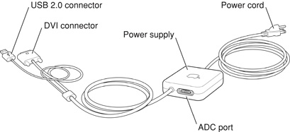
Figure 3-8 shows the contact configuration for the DVI connector; Table 3-10 lists the signals and pin assignments.
The graphics data sent to the digital monitor use transition minimized differential signaling (TMDS). TMDS uses an encoding algorithm to convert bytes of graphics data into characters that are transition-minimized to reduce EMI with copper cables and DC balanced for transmission over fiber optic cables. The TMDS algorithm also provides robust clock recovery for greater skew tolerance with longer cables or low-cost short cables.
For information about TMDS, see the reference listed in “Digital Visual Interface.”
DVI to Video Adapter
The Power Mac G5 computer supports an optional DVI to S-video/composite adapter that provides S-video and composite output to a PAL or NTSC video monitor or VCR. When a display is connected by way of the video adapter, the computer detects the type of adapter and enables the composite and S-video outputs. The settings for the resolutions and standards (NTSC or PAL) are then selectable in the System Preferences Displays pane.
Note: The DVI to video adapter does not come packaged with the Power Mac G5 computer and must be purchased separately.
The video output connector is a 7-pin S-video connector. shows the arrangement of the pins and Table 3-11 shows the pin assignments on the composite out and S-video connector.
Pin number | S-video output connector |
|---|---|
1 | Analog GND |
2 | Analog GND |
3 | Video Y (luminance) |
4 | Video C (chroma) |
5 | composite video |
6 | Unused |
7 | Unused |
The Power Mac G5 computer provides video output at picture sizes and frame rates compatible with the NTSC and PAL standards; the picture sizes are listed in Table 3-12. Those picture sizes produce under-scanned displays on standard monitors.
Picture size | Pixel depth |
|---|---|
800 by 600 | 24 bpp |
832 by 624 | 24 bpp |
1024 by 768 | 24 bpp |
Dual Display Extended and Mirror Modes
The Power Mac G5 is equipped with an ADC port for connecting an Apple display and a DVI port for a second digital display. Through these two ports, the Power Mac G5 supports dual displays in both extended desktop and video mirroring modes. Extended desktop mode lets users distribute work across two displays, increasing the amount of visible desktop space. Video mirroring mode displays the same information on both monitors, enabling the control of a presentation on one display, while allowing an audience to watch the presentation on a second display or projector. The Power Mac G5 can power two Apple Cinema HD Displays at a cumulative pixel resolution of 3840x1200.
To switch between extended desktop and video mirroring modes, enable the “Mirror Displays” option on the Arrangement tab in the Displays pane of System Preferences.
The scaling function is available when both monitors (main via ADC and second via DVI) are operating and the mirror mode is selected. Either monitor could have black borders during mirroring, depending on the supported timings between the two displays and on the monitor’s selection algorithm. Both displays show full-sized images only when the resolutions match. Both displays can operate with other resolution settings, but in mirror mode, one of them has a display that is smaller than the full screen and has a black border around it.
© 2003, 2004 Apple Computer, Inc. All Rights Reserved. (Last updated: 2004-06-29)