Overview of the Xserve G5
The Xserve G5 is the Macintosh server platform using the PowerPC G5 microprocessor. It has a rack-mount enclosure and includes server-oriented features such as ample internal storage, hot-pluggable drives, hardware monitoring, and easy tool access.
This developer note includes both the standard three drive bay configuration and the basic cluster node single drive bay configuration. Both configurations feature high performance I/O, high speed network I/O, and 400 MHz ECC DDR memory. The differences in the two Xserve G5 configurations are identified throughout this document. When not specifically stated, the information presented in this note is for the both configurations.
In this section:
Hardware Features
Features of the Enclosure
System Software
Hardware Features
Table 1-1 below, provides a list of the hardware features of the Xserve G5 and Table 1-2 provides a list of the hardware features of the Xserve G5 cluster node configuration. New features are listed first. Each of the major features is described more fully later in this note, as indicated by the cross references.
New Features | |
Microprocessor speed | Single 2.0 GHz or dual 2.3 GHz PowerPC G5 microprocessors. See “PowerPC G5 Microprocessor.” |
Optical drive | Contains a Combo (CD-RW/DVD-ROM) drive; see “Combo Drive .” A SuperDrive (CD-RW/DVD-RW) is available as a build-to-order option; see “SuperDrive (Optional).” |
RAM | Eight slots (four pairs of two) for 184-pin DIMMs (dual inline memory modules) using ECC (error correcting code) DDR400 (double data rate) dynamic RAM devices. Supports a maximum of 8 GB. See “RAM Expansion.” |
Hard disk | 7200-rpm, hot-pluggable, 80 GB hard disk drive with 8MB cache in one of the three drive bays. Build-to-order 250 GB or 400 GB drives available for a maximum of 1.2 TB internal storage. |
Additional Features | |
Hyper Transport | A high-speed bus architecture between the memory controller and device I/O. For more information, see “HyperTransport Technology.” |
Processor system bus | 64-bit processor interface bus running at half the speed of the system microprocessor. See “Processor Bus.” |
Memory caches | Internal 512 KB level 2 cache per processor. See “Cache Memory.” |
ROM | ROM-in-RAM implementation with 2 MB of boot ROM. For information about the ROM, see “Boot ROM.” For information about the ROM-in-RAM implementation, see the references listed in “ROM-in-RAM Architecture.” |
Hard disk drive bays | Up to three drive bays for serial ATA (SATA) drives with independent buses and support for hot-pluggable drives using Apple Drive Modules. See “Hard Disk Drives.” |
USB 2.0 ports | Two USB 2.0 ports. See “USB Ports.” |
Ethernet | Dual Ethernet ports for 10Base-T, 100Base-T, or 1000Base-T operation. See “Ethernet Ports .” |
FireWire ports | Two FireWire 800 ports on back panel and one FireWire 400 on front. See “FireWire Ports.” |
PCI-X card expansion slots | Two PCI-X expansion slots for PCI or PCI-X cards. See “PCI or PCI-X Expansion Slots .” |
System Monitoring | The system monitors the fan speeds and reports if speeds are outside acceptable range, indicating that a fan needs service. |
New Features | |
Microprocessor speed | Dual 2.3 GHz PowerPC G5 microprocessors. See “PowerPC G5 Microprocessor.” |
RAM | Eight slots (four pairs of two) for 184-pin DIMMs (dual inline memory modules) using ECC (error correcting code) DDR400 (double data rate) dynamic RAM devices. Supports a maximum of 8 GB. See “RAM Expansion.” |
Additional Features | |
Memory caches | Internal 512 KB level 2 cache per processor. See “Cache Memory.” |
Processor system bus | 64-bit processor interface bus running at half the speed of the system microprocessor. See “Processor Bus.” |
Hyper Transport | A high-speed bus architecture between the memory controller and device I/O. For more information, see “HyperTransport Technology” |
ROM | ROM-in-RAM implementation with 2 MB of boot ROM. For information about the ROM, see “Boot ROM.” For information about the ROM-in-RAM implementation, see the references listed in “ROM-in-RAM Architecture.” |
Hard disk drive bay | One serial ATA (SATA) Apple Drive Module with support for hot-pluggable drive. See “Hard Disk Drives.” |
Hard disk | 7200-rpm, hot-pluggable, 80 GB hard disk drive with 8MB cache. Build-to-order 250 GB or 400 GB drives available. |
USB 2.0 ports | Two USB 2.0 ports. See “USB Ports.” |
Ethernet | Two Ethernet ports for 10Base-T, 100Base-T, or 1000Base-T operation. See “Ethernet Ports .” |
FireWire ports | Two FireWire 800 ports on back panel and one FireWire 400 on front. See “FireWire Ports.” |
PCI-X card expansion slots | Two PCI-X expansion slots for PCI or PCI-X cards. See “PCI or PCI-X Expansion Slots .” |
System Monitoring | The system monitors the fan speeds and reports if speeds are outside acceptable range, indicating that a fan needs service. |
Features of the Enclosure
The Xserve G5 has a rack optimized enclosure that is 1U (1.75” tall) and conforms to the industry standard for 19-inch rack mounting. For information about the standard, see the reference at “EIA Rack Standards.”
All of the components in the server are accessible without the use of special tools.
Figure 1-1 shows the front panel of the standard Xserve G5, which has a power button and light, an enclosure lock and status light, a system identifier button and light, a FireWire 400 port, Ethernet link lights, a slot-loading optical drive, up to three serial ATA drive modules, and a two-by-eight set of system activity lights.
Note: Depending on the configuration of your Xserve G5, the appearance may differ slightly from the illustrations.
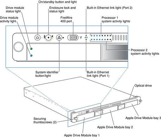
Figure 1-2 shows the back panel of the slot load and cluster node Xserve G5, which are basically the same. The back panel has an A/C power socket, two gigabit Ethernet ports, two FireWire 800 ports, a system identifier button and light, two USB 2.0 ports, a serial console port, and two PCI-X card slots. An optional video card can occupy one of the PCI-X slots in the standard configuration (not supported in the cluster node configuration).
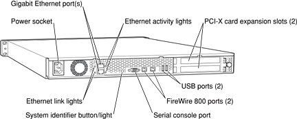
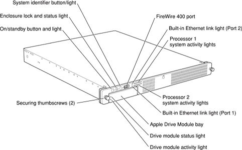
Figure 1-3 shows the front panel of the cluster node Xserve G5, which has a power button and light, an enclosure lock and status light, a system identifier button and light, a FireWire 400 port, two Ethernet link lights, a two-by-eight set of system activity lights, and drive module and lights. Additional drive modules cannot be installed in the cluster node configuration. The rear panel is mostly the same as the slot load configuration and is shown in Figure 1-2.
System Activity Lights Definitions
The system identifier button on the server’s front panel can be used to initiate a limited number of firmware boot commands without connecting a keyboard or monitor. For instructions on entering the commands, refer to the Xserve G5 User’s Guide that shipped with your computer.
The bottom row of system activity lights on the Xserve G5 (shown in Figure 1-1 and Figure 1-3 indicates the state of the computer when commands are entered and during normal operation. The lights are referenced from right to left, with light one being the rightmost and light 8 being the leftmost. The bottom row of system activity lights are defined below in Table 1-3.
Light 1(far right) | Start up from a system disc in the optical drive (also ejects a disc already in the optical drive). |
Light 2 | Start up from a network server (NetBoot). |
Light 3 | Start up from the internal drive (leftmost drive if more than one). |
Light 4 | Bypass the current startup disk and start up from any other available startup disk. |
Light 5 | Begin target disk mode (all drives, including the optical drive, will show up). |
Light 6 | Restore the system’s default settings (reset NVRAM). |
Light 7 | Enter Open Firmware (via the serial port if no monitor and keyboard are connected). |
Light 8 | Put the system into diagnostic hardware test mode. |
Note: If Open Firmware Security is turned on, front panel mode is not available. In this case, the two rows of system activity lights flash twice when you try to enter a command with the system identifier and the system resumes its regular startup sequence.
System Software
The Xserve G5 comes with Mac OS X Server installed. The Xserve G5 cluster node comes with a 10 user license of Mac OS X Server installed.
Server Software Features
Here is a list of the key features of the system software on the Xserve G5. For information on installing or updating software, see the Xserve G5 User’s Guide. For information on server topics, including server command line tools, refer to the Mac OS X Server Documentation website at http://www.apple.com/server/documentation.
UPS support: Mac OS X Server contains an enhanced version of UPS support that supports serial and USB UPS devices. The Power Manager has been enhanced to allow UPS vendors to communicate directly with the Power Manager to control their UPS hardware. UPS settings can be made in the Energy Saver preference pane and with the
pmsetcommand. Seeman pmsetfor more information.The Server Monitor application shows status of the UPS.
An editable UPS shutdown script that will run when the machine powers down because of UPS is available in the
/user/libexec/upsshutdowndirectory.Auto restart after power failure: Xserve G5 hardware supports auto restart after power failure through software control. In the event of a power outage, an Xserve G5 unit detects the return of power and performs an automatic restart.
Also supported is staggered start-up after power failure, using the following terminal commands to alter the start-up times of a rack of machines by increments of 30 seconds to avoid overloading power.
systemsetup -getwaitforstartupafterpowerfailure— to get the number of seconds after which the computer will start up after a power failure.systemsetup -setwaitforstartupafterpowerfailure <seconds>— to set the number of seconds after which the computer will start up after a power failure, where <seconds> must be a multiple of 30 seconds.Software administration tools: The Administration Tools CD provides a rich set of tools for remote hardware monitoring and remote software management. The documentation (“man pages”) for these tools is located in various subdirectories of the
/usrdirectory. The Terminal application in Mac OS X provides access to a full array of command-line tools for software and system administration.Headless access: If your Xserve G5 configuration does not include a video card and mouse, headless access is available through the command line. In a headless configuration, use the
softwareupdatecommand to update your system software; refer to Command-Line Administration on the Mac OS X Server Documentation website.SNMP: Implemented in Mac OS X Server, SNMP stack allows Xserve G5 monitoring by standard SNMP management consoles. In addition to the standard SNMP MIBs, Mac OS X Server provides MIBs for its core services. SNMP support is currently read-only.
Automatic NetBoot: Xserve G5 can automatically invoke NetBoot by opening the drive handles. For information, refer to http://apple.com/server/documentation.
Security Features
Here are the key security features supported by the system software on the Xserve G5.
Secure ports: Xserve G5 prevents mounting of CDs as well as hot-plugged USB and FireWire hard drives by means of an enclosure lock.
Secure remote management: Xserve G5’s remote monitoring and management tools run over encrypted links.
Storage Support
Here is a list of the key software features relating to hard disk storage on the Xserve G5.
Disk utilities tool: You can use the filesystem consistency check and interactive repair tool, included with Mac OS X, to work on the Xserve G5’s file system. For more information, launch the Terminal application in Mac OS X and enter the following line after the prompt:
man diskutilRemote volume configuration: The system software can remotely configure newly mounted volumes.
USB and FireWire alerts: Xserve G5’s keyswitch security prevents unauthorized hot-plugging and mounting of a USB or FireWire hard drive. When the keyswitch is locked, the CD is ejected. In addition, the Security System pane provides configuration support for USB keyboard and mouse.
Management Support
Here are some of the management support features of the system software on the Xserve G5.
Command Line Tools
The following command line tools provide management support. Use the man command to display usage syntax.
systemsetup —to change the system preferences
networksetup — to change the network settings
pmset —to change the power management settings
SNMP Implementation
The SNMP implementation in Mac OS X Server allows the Xserve G5 to be monitored by standard SNMP management consoles.
The SNMP implementation on the Xserve G5 is based on the net-snmp project. For more information, see the net-snmp page on the World Wide Web at
Computer Feature Identification
Rather than reading the box flag or the model string and then making assumptions about the server’s features, applications that need to find out the features of the server should use IORegistry calls to test for the features they require. IORegistry calls are part of the I/O Kit API. For more information, see the references listed at “I/O Kit.”
Asset management software that reports the kind of computer it is running on can obtain the value of the model property from the device tree root node. The entry banner of the Open Firmware user interface software displays the model property. Or, to display the model property from within the Open Firmware user interface, type the following to display the model property:
0 > dev /
0 > .properties
The "dev /" selects the root device and ".properties" displays all properties of the device selected.
For both Xserve G5 configurations, the value of the model property is RackMac3,1.
Velocity Engine Acceleration
The Velocity Engine (an implementation of AltiVec) is the vector processing unit in the PowerPC G5 microprocessor. Some system software has been modified to take advantage of the accelerated processing that the Velocity Engine makes possible. System software has also been modified to support low-level operations using the Velocity Engine.
For complete information on the Velocity Engine, refer to the following Apple website:
http://developer.apple.com/hardwaredrivers/ve/index.html
© 2002, 2008 Apple Inc. All Rights Reserved. (Last updated: 2008-02-21)