PATH
The optional SetGamma control routine sets the gamma table in the driver that corrects RGB color values.
OSErr = Control(theDeviceRefNum, cscSetGamma, &theVDGammaRecord );
The gamma table compensates for nonlinearities in a display's color response by providing either a function or a lookup value that associates each displayed color with an absolute RGB value.
To reduce visible flashes resulting from color table changes, the SetGamma routine works in conjunction with the SetEntries control routine on indexed devices. The SetGamma routine first loads new gamma correction data into the driver's private storage; the next SetEntries control call applies the gamma correction as it changes the CLUT. SetGamma calls are always followed by SetEntries control calls on indexed devices.
For direct devices, the SetGamma routine first sets up the gamma correction data table. Next, it synthesizes a black-to-white linear ramp color table. Finally, it applies the new gamma correction to the color table and sets the data directly in the hardware. Proper correction is particularly important to image-processing applications running on direct devices.
Displays that do not use gamma table correction tend to look oversaturated and dark. Although determining the correct values for a gamma table can be difficult without special tools, the table's contribution to image quality can be striking.
If NIL is passed for the csGTable value, the driver should build a linear ramp in the gamma table to allow for an uncorrected display.
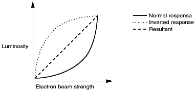
On a cathode ray tube, phosphors luminesce when they are struck by an electron beam. Unfortunately, there is not a direct correspondence between the luminance of the phosphors and the strength of the electron beam. To create a linear relationship, the actual response is measured and the inverse of its deviation from linearity is applied as a correction factor. Figure 13-1 illustrates this process.
Figure 13-1 Luminosity and electron beam strength

Although this example is described in terms of electron beams and phosphors of a cathode ray tube, similar relationships exist between diode current and LED brightness in active matrix displays.