Devices and Ports
This chapter describes both the built-in I/O devices and the ports for connecting external I/O devices. Each of the following sections describes an I/O port or device.
In this section:
USB 2.0 Ports
FireWire Ports
Ethernet Port
Internal Modem
AirPort Extreme
Bluetooth Technology
Hard Disk Drive
SuperDrive
Trackpad
Keyboard
Flat-Panel Display
External Monitors
External Video Port
Sound System
USB 2.0 Ports
The 17-inch PowerBook G4 has two external USB 2.0 ports that can be used to connect additional I/O devices such as a USB mouse, printers, scanners, and storage devices.
The USB ports on the 17-inch PowerBook G4 comply with the Universal Serial Bus Specification 2.0. For more information about USB on Macintosh computers, consult the references at “USB Interface.”
Note: Some self-powered USB devices inadvertantly violate electrical specifications for self-powered USB devices. For details and ways to avoid this design issue, refer to http://developer.apple.com/qa/hw/hw82.html.
USB Connectors
The USB ports use USB Type A connectors, which have four pins each. Two of the pins are used for power and two for data. Figure 3-1 is an illustration of a Type A port and matching connector. Table 3-1 shows the pin assignments.
Pin | Signal name | Description |
|---|---|---|
1 | VCC | +5 VDC |
2 | D– | Data – |
3 | D+ | Data + |
4 | GND | Ground |
The computer provides 5-volt power at 500 mA for each of the two ports.
The external USB 2.0 ports support low-speed (1.5 Mbps), full-speed (12 Mbps), and high-speed (480 Mbps) data transfers. High-speed operation requires the use of shielded cables.
The 17-inch PowerBook G4 supports all four data transfer types defined in the USB specification.
USB devices can provide a remote wakeup function for the computer. The USB root hub in the computer is set to support remote wakeup whenever a device is attached to the bus.
USB Class Drivers
Class drivers are software components that are able to communicate with many USB devices of a particular kind. If the appropriate class driver is present, any number of compliant devices can be plugged in and start working immediately without the need to install additional software.
FireWire Ports
The 17-inch PowerBook G4 has one FireWire 400 (IEEE 1394a) port and one FireWire 800 (IEEE 1394b) port. Both FireWire ports
support booting the system from a mass storage device
support target disk mode
The two FireWire ports share a single power supply that can provide up to 14 watts total. Both ports are on the same FireWire bus and can connect to up 62 other FireWire devices.
The FireWire hardware and software provided with the 17-inch PowerBook G4 are capable of all asynchronous and isochronous transfers defined by IEEE standard 1394a and 1394b.
For additional information about the FireWire interface and the Apple API for FireWire device control, refer to the resources listed at “FireWire Interface.”
FireWire 400 Connector
The 6-pin FireWire 400 technology
supports serial I/O at 100, 200, and 400 Mbps
provides up to 7 watts of power when the computer system is on or when the power adapter is connected and in sleep mode
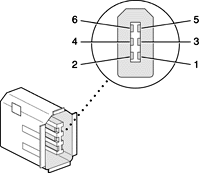
The FireWire 400 connector has six contacts, as shown in Figure 3-2. The connector pin assignments are shown in Table 3-2.
When the computer is on or the power adapter is connected, the power pin provides a maximum voltage of 12.8 V (no load) and 7 W power per port. Maximum output current for both ports combined is 1.5 A and is controlled by a self-resetting fuse.
Pin 2 of the 6-pin FireWire connector is ground for both power and the inner cable shield. If a 4-pin connector is used on the other end of the FireWire cable, its shell should be connected to the wire from pin 2.
The signal pairs are crossed in the cable itself so that pins 5 and 6 at one end of the cable connect with pins 3 and 4 at the other end. When transmitting, pins 3 and 4 carry data and pins 5 and 6 carry clock; when receiving, the reverse is true.
FireWire 800 Connector
The FireWire 800 port on the 17-inch PowerBook G4 is based on IEEE 1394b and enables a 800 Mbps transfer rate. FireWire 800 uses a 9-pin connector and is backwards compatible with original 1394 FireWire devices with 6-pin or 4-pin connectors. With the appropriate cable, the new 9-pin port works seamlessly with legacy FireWire devices. Cables are available to go from both 6-pin and 4-pin connectors to a 9-pin, and 9-pin to 9-pin.
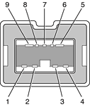
The 9-pin FireWire 800 connector is shown in Figure 3-3. Its connector signals and pin assignments are shown in Table 3-3.
VP (pin 8) provides up to 7 W power, shared with the other FireWire connectors. The voltage on the power pin is approximately 12.8 V.
The 9-pin FireWire 800 port is capable of operating at 100, 200, 400, and 800 Mbps, depending on the device to which it is connected. The FireWire 800 port is bilingual in that it supports both IEEE 1394a and 1394b. Using a cable with a 9-pin connector at one end and a 4-pin or 6-pin connector at the other, the 9-pin port is capable of directly connecting to all existing FireWire devices. Using a cable with 9-pin connectors at both ends, the 9-pin port is capable of operating at 800 Mbps.
The IEEE 1394b standard defines long-haul media using Cat 5 UTP and several kinds of optical fiber. The 17-inch PowerBook G4 is interoperable with such cables but cannot be directly connected to them. To use long-haul cables, connect the computer to a 1394b hub that has the desired kind of long-haul connectors. If the hub has a bilingual port, that port can be connected to any of the computer’s FireWire ports. If the hub has a beta-only port, it can be connected only to the computer’s 9-pin port.
FireWire Device Programming
Mac OS X includes general support for the FireWire bus and specific support for various kinds of FireWire devices and protocols. Developers can use the built-in support or provide additional applications and drivers for use with their products.
The general FireWire services will configure the FireWire bus, scan the bus for new devices, and allow multiple drivers and devices to share a single FireWire interface cooperatively. The general services also publish information about the bus and the devices in the IO Registry, so that IO Kit can match protocols and drivers to each connected FireWire device.
The specific device and protocol support in Mac OS X as provided with the 17-inch PowerBook G4 includes the following:
General services for Serial Bus Protocol 2 (SBP-2) and support for most mass storage devices using SBP-2, such as hard disk drives, optical drives, flash card readers, Target Disk Mode (see “Target Disk Mode”), and the iPod. Mac OS X can boot from most of these devices.
General services for the Audio Video Control (AV/C) protocol and support for most digital video (DV) cameras and decks using this protocol, including video capture through standard QuickTime APIs.
A QuickTime device driver for IIDC/DCAM type cameras such as the iSight.
A network device driver supporting IP (Internet Protocol) over FireWire according to IEEE RFC 2734.
Additional services for user-space and kernel access to all FireWire resources.
For information on writing FireWire drivers or applications, download the latest FireWire SDK from http://developer.apple.com/sdk/.
For additional references, refer to “FireWire Interface.”
Target Disk Mode
One option at boot time is to put the computer into a mode of operation called target disk mode.
When the 17-inch PowerBook G4 is in target disk mode and connected to another Macintosh computer by a FireWire cable, the 17-inch PowerBook G4 operates like a FireWire mass storage device with the SBP-2 (Serial Bus Protocol) standard. Target disk mode has two primary uses:
high-speed data transfer between computers
diagnosis and repair of a corrupted internal hard drive
The 17-inch PowerBook G4 can operate in target disk mode as long as the other computer has a FireWire 1394a or 1394b port and is running either Mac OS X (any version) or Mac OS 9 with FireWire software version 2.3.3 or later.
To put the computer into target disk mode, hold down the T key while the computer is starting up. When Open Firmware detects the T key during the boot process, it transfers control to special Open Firmware code.
To take the computer out of target disk mode, press the power button.
Note: The 17-inch PowerBook G4 is designed to use the 65 W Apple Portable Power Adapter which ships with it. A 45 W Apple portable power adapter works with the 17-inch PowerBook G4, but may provide insufficient power during some activities and power may be drawn temporarily from the battery. Therefore a 45 W power adapter is not recommended.
Ethernet Port
The 17-inch PowerBook G4 has a built-in Ethernet port that supports 10Base-T, 100Base-T, and 1000Base-T transfer rates. In operation, the actual speed of the link is auto-negotiated between the computer’s PHY device and the network hub or switch to which it is connected.
The connector for the Ethernet port is an RJ-45 connector on the right side of the computer. Table 3-4 shows the signals and pin assignments for 10Base-T and 100Base-T operation. Table 3-5 shows the signals and pin assignments for 1000Base-T operation.
To interconnect two computers for 1000Base-T operation, you must use 4-pair cable (Category 5 or 6).
The Ethernet port on the 17-inch PowerBook G4 supports Auto-MDIX. It switches between MDI (Medium Dependent Interface) and MDI-X operation automatically, so it can be connected to another device by either a straight-through cable or a cross-over cable.
The Ethernet interface in the 17-inch PowerBook G4 conforms to the ISO/IEC 802.3 specification, where applicable, and complies with IEEE specifications 802.3i (10Base-T), 802.3u-1995 (100Base-T), and 802.3ab (1000Base-T).
Internal Modem
The 17-inch PowerBook G4 comes with a built-in modem. The connector for the modem is an RJ-11 connector on the left side of the computer.
The modem has the following features:
modem bit rates up to 56 Kbps (supports V.34, V.90, and V.92 modem standards)
fax modem bit rates up to 14.4 Kbps
The modem is connected to an internal USB port and is a vendor-specific USB device. The modem driver controls the modem hardware and presents a virtual serial port to the operating system and applications. Applications that bypass the operating system’s modem driver and communicate directly with the SCC will not work properly.
Note: 56 Kbps technology refers to download speeds only and requires compatible modems at server sites. Other conditions may limit modem speed. FCC limitations allow a maximum of 53 Kbps during download transmissions.
AirPort Extreme
The 17-inch PowerBook G4 supports AirPort Extreme, a fully-integrated, internal wireless LAN module that is fully compliant with the IEEE 802.11g standard. By communicating wirelessly with a base station, AirPort Extreme can be used for internet access, email access, and file exchange. A base station provides the connection to the Internet or the bridge between the wireless signals and a wired LAN or both. The AirPort Extreme Base Station has connectors for a wired LAN, a DSL or cable modem, or a standard telephone line using the optional 56K modem that is built-in on some models.
AirPort Extreme transmits and receives data at speeds up to 54 Mbps, comparable to wired networking speeds. AirPort Extreme is also compatible with other devices that follow the IEEE 802.11b standard, including PC's. For more information about compatibility, see the reference at “Wireless Networks.”
Note: As is the case with the existing IEEE 802.11b standard, actual data throughput speeds will be lower than the indicated maximum connection speeds. Inherent in wireless LAN systems, bandwidth overhead is required for wireless routing, scrambling, security error correction, and other processes.
Data Security
AirPort Extreme has several features designed to maintain the security of the user’s data.
In 802.11b mode, the system uses direct-sequence spread-spectrum (DSSS) technology that uses a multi-bit spreading code that effectively scrambles the data for any receiver that lacks the corresponding code.
The system can use an Access Control List of authentic network client ID values (wireless and MAC addresses) to verify each client’s identity before granting access to the network.
When communicating with a base station, AirPort Extreme uses 64-bit and 128-bit WEP encryption to encode data while it is in transit. Additional security features may be available via firmware upgrades as 802.11 enhancements are ratified by IEEE.
The AirPort Extreme Base Station can be configured to use NAT (Network Address Translation), protecting data from Internet hackers.
The AirPort Extreme Base Station can authenticate users by their unique Ethernet IDs, preventing unauthorized computers from logging into your network. Network administrators can take advantage of RADIUS compatibility, used for authenticating users over a remote server. Smaller networks can offer the same security using a local look-up table located within the base station.
As an additional data security measure, VPN can be used in conjunction with the AirPort Extreme data security.
AirPort Extreme Hardware
AirPort Extreme is a fully-integrated, wireless LAN module based on the IEEE 802.11g standard using both OFDM (orthogonal frequency-division multiplexing) and DSSS technologies. Using DSSS, AirPort Extreme is interoperable with PC-compatible wireless LANs that conform to the 802.11b standard at speeds of 11 Mbps, 5.5 Mbps, 2 Mbps, and 1 Mbps. Using OFDM, AirPort Extreme is compatible with all 802.11g standard speeds.
Two antennas are built into the computer, on either side of the flat-panel display. One antenna is always used for transmitting. Either of the two antennas may be used for receiving. Using a diversity technique, AirPort Extreme may select the antenna that gives the best reception. The secondary antenna is used for Bluetooth.
AirPort Extreme Software
The 17-inch PowerBook G4 includes software for setting up and using AirPort Extreme:
AirPort Extreme Setup Assistant, an easy-to-use program that guides users through the steps necessary to set up AirPort Extreme or set up an AirPort Extreme Base Station.
Users can switch between wireless networks and can create and join peer-to-peer networks. These functions are accessed via the AirPort Extreme status menu.
AirPort Extreme Admin Utility, a utility for advanced users and system administrators. With it the user can edit the administrative and advanced settings needed for some advanced configurations.
Bluetooth Technology
Bluetooth is a fully integrated, open specification that enables short-range wireless connections between desktop and laptop computers and a host of other peripheral devices. Bluetooth support is built into Mac OS X and compliant with Bluetooth specification v1.1. It operates on a globally available 2.4 GHz frequency band (ISM band) for worldwide compatibility and has a maximum throughput of 1Mbps.
The Bluetooth technology supports the following profiles:
synchronization —enables synchronization of devices over Bluetooth
serial —provides a wireless serial connection to other Bluetooth devices
dial-up networking (DUN) — enables a mobile phone to act as a modem
object push —enables the transfer of files between Bluetooth devices
human interface device (HID) — enables the use of Bluetooth input devices (keyboards and mice)
hardcopy cable replacement profiler (HCRP) — defines functionality that enables a Bluetooth link to replace a printer cable, allowing standard Bluetooth drivers to be adapted to use Bluetooth links.
Bluetooth and AirPort Extreme share the antennas in the 17-inch PowerBook G4’s display housing.
Internal, fully-integrated Bluetooth is standard on the 17-inch PowerBook G4.
For more information on Bluetooth technology, refer to “Bluetooth.”
Hard Disk Drive
The 17-inch PowerBook G4 has a 4200 rpm internal hard disk drive with a storage capacity of 80 GB; available as a build to order option is an 80 GB 5400 rpm hard drive. The drive has fluid dynamic bearings for quieter operation.The drive uses the Ultra ATA-100 (IDE, integrated drive electronics) interface and is ATA-6 compatible. Data Transfer Mode for the drive is ATA-100.
The software that supports the internal hard disk is the same as that in previous models with internal IDE drives and includes DMA support.
To obtain the reference documents listed here, see the reference links at “ATA Devices.”
Hard Disk Dimensions
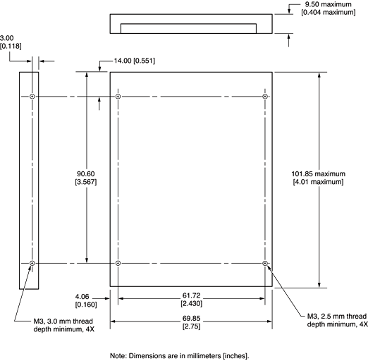
Figure 3-4 shows the maximum dimensions of the hard disk and the location of the mounting holes. The minimum clearance between any conductive components on the drive and the bottom of the mounting envelope is 0.5 mm.
Hard Disk Connector
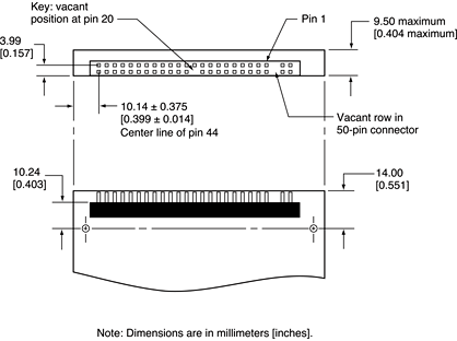
The internal hard disk has a 48-pin connector that carries both the ATA signals and the power for the drive. The connector has the dimensions of a 50-pin connector, but with one row of pins removed, as shown in Figure 3-5. The remaining pins are in two groups: pins 1–44, which carry the signals and power, and pins 45–48, which are reserved. Pin 20 has been removed, and pin 1 is located nearest the gap, rather than at the end of the connector.
Signal Assignments
Table 3-6 shows the signal assignments on the 44-pin portion of the hard disk connector. A slash (/) at the beginning of a signal name indicates an active-low signal.
/IOCS16 is not used; see Table 3-7.
ATA Signal Descriptions
Table 3-7 describes the signals on the ATA hard disk connector.
The built-in ATA devices are connected to the I/O bus through bidirectional bus buffers.
SuperDrive
The 17-inch PowerBook G4 has a slot-loading SuperDrive. The SuperDrive can read and write DVD media and CD media as shown in Table 3-8. The SuperDrive drive also provides DVD-Video playback.
The Apple SuperDrive is an ATAPI drive and writes to DVD-R 4.7 gigabyte General Use media. These discs are playable in most standard DVD players and computer DVD-ROM drives.
Digital audio signals from the SuperDrive can be played through the sound outputs under the control of the System Preferences.
Important: The SuperDrive supports only 12 cm disc media. It does not support 8 cm discs or noncircular media.
Trackpad
The pointing device in the 17-inch PowerBook G4 is a trackpad. The trackpad is a solid-state device that emulates a mouse by sensing the motions of the user’s finger over its surface and translating those motions into ADB commands.
The user makes selections either by pressing the trackpad button (below the trackpad) or by tapping and double tapping on the pad itself. The trackpad responds to one or two taps on the pad itself as one or two clicks of the button. The user can tap and drag on the trackpad in much the same manner as clicking and dragging with the mouse. The tap and double-tap functions are optional and can be activated or deactivated by means of the mouse pane in System Preferences.
The trackpad on the 17-inch PowerBook G4 has palm-rejection capabilities that help prevent unintended trackpad input while typing is being performed. When the “Ignore accidental trackpad input” checkbox is selected on the keyboard and mouse pane of Systems Preferences, the system software attempts to filter out unintended contact with the trackpad. The trackpad will not respond when a mouse is present and the “Ignore accidental trackpad input” checkbox is selected on the mouse pane of Systems Preferences.
Note: If the trackpad is not responding to intended input, check to see if the “Ignore accidental trackpad input” checkbox is selected.
Keyboard
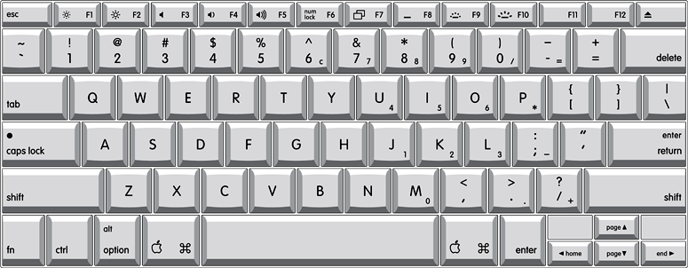
The keyboard is a full-size, 19 mm pitch, low-profile design with a row of function keys and cursor motion keys in an inverted-T arrangement. A dedicated media eject key is located to the right of the F12 function key.
The 17-inch PowerBook G4 has a backlit keyboard and ambient light sensors that control the brightness of the display and the keyboard backlighting. In low light, the computer automatically illuminates the backlit keyboard and lowers the display brightness. As light levels increase, the display brightness is re-adjusted automatically and the keyboard backlighting is turned off. There are two light sensors, one under each speaker grill.
Access to internal components and expansion connectors is no longer via the keyboard, so the keyboard is not latched for removal. Access to the memory cards is via the RAM expansion slot and is explained in “RAM Expansion Slots.”
Changing the Operation of the Keyboard
Several of the keys on the keyboard have more than one mode of operation.
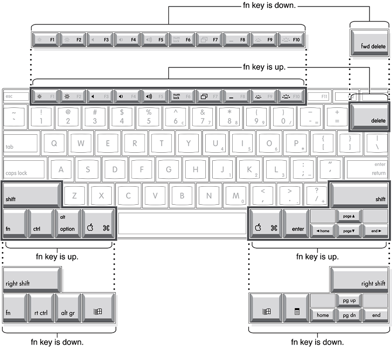
Function keys F1–F10 can also control features such the display brightness, the speaker volume, the dual display feature, the Num Lock function, and the illuminated keyboard brightness. Refer to Table 3-9 for the entire list. A media eject key is located to the right of the F12 function key.
Certain control keys can be used as page-control keys.
The keys on the right side of the keyboard can be used as a numeric keypad.
The next sections describe these groups of keys and the way their alternate modes of operation are selected by using the Fn key, and the Num Lock key.
Keyboard Illustrations
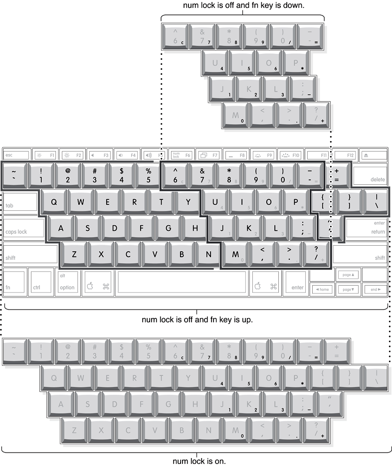
Figure 3-6 shows the actual appearance of the keyboard. Figure 3-7 shows the alternate modes of operation of the function and control keys. Figure 3-8 shows the embedded numeric keypad.
Figure 3-7 and Figure 3-8 include duplicate versions of some keys in order to show their alternate modes of operation. In some cases, the alternate key captions shown in the figures do not appear on the keyboard. For the actual appearance of the keyboard, refer to Figure 3-6.
Using the Fn Key
Pressing the Fn key affects three sets of keys: the function keys F1–F12, the embedded numeric keypad, and certain modifier keys.
It toggles the function keys between their control-button operation and their F1–F10 functions, as shown in Table 3-9 and Figure 3-7.
It selects the embedded numeric keypad on the right portion of the alphanumeric keys, as shown in Table 3-10 and Figure 3-8.
It changes certain control keys, including the cursor control keys, to page control keys, as shown in Table 3-11 and Figure 3-8.
Note: In Mac OS X, a third-party utility is needed to implement user-programmable function key assignments.
Using the Num Lock Key
Pressing the Num Lock key affects two sets of keys: the embedded keypad and the rest of the alphanumeric keys.
It selects the embedded numeric keypad, as shown in Table 3-10 and Figure 3-8.
It makes the rest of the alphanumeric keys functionless (NOPs), as shown in Figure 3-8.
The Function Keys
Table 3-9 defines the default operation of the function keys. The "Use the F1-F12 keys for custom actions" checkbox in the Keyboard and Mouse pane in System Preferences allows you to toggle the default operation of these keys to custom actions. When this checkbox is enabled, the function keys operate as F1 through F12 keys that can be customized within individual software applications. Holding down the fn key while the checkbox is enabled, will go back to perform the default action that is listed in Table 3-9.
The Embedded Keypad
A certain group of alphanumeric keys can also function as an embedded keypad. The user selects this mode by using the Fn key or the Num Lock key. Figure 3-8 shows the keys making up the embedded keypad and Table 3-10 lists them.
Key name | Keypad function | Key name | Keypad function | ||
|---|---|---|---|---|---|
6 | Clear | P | * (multiply) | ||
7 | 7 | J | 1 | ||
8 | 8 | K | 2 | ||
9 | 9 | L | 3 | ||
0 | / (divide) | ; | – (subtract) | ||
- | = (equals) | M | 0 | ||
U | 4 | , | NOP | ||
I | 5 | . | . (decimal) | ||
O | 6 | / | + (add) |
When the embedded keypad is made active by the Num Lock key, the other alphanumeric keys have no operation (NOP), as shown in Figure 3-8. The affected keys include certain special character keys: plus and equal sign, right and left brackets, vertical bar and backslash, and straight apostrophe.
Other Control Keys
The cursor control keys can also be used as page control keys. Other control keys can take on the functions of certain keys on a PC keyboard, for use with PC emulation software. The Fn key controls the modes of operation of this group of keys. Table 3-11 is a list of these keys and their alternate functions. These control keys are also show in Figure 3-8.
Flat-Panel Display
The 17-inch PowerBook G4 has a built-in, wide-screen, 100 dpi, color flat-panel display with a resolution of 1440 by 900 pixels and measures 17 inches diagonally.
The display is backlit by a cold cathode fluorescent lamp (CCFL). The display uses TFT (thin-film transistor) technology for high contrast and fast response.
In addition to its native resolution (1440 by 900) the display also supports several non-native resolutions, as shown in Table 3-12. The graphics controller IC includes a scaling function that expands displays with those smaller resolutions to fill the screen.
The display’s native resolution, 1440 by 900, has an aspect ratio of 16:10. When selecting a picture resolution with an aspect ration of 4:3, the user can choose to have it displayed with square pixels and black margins on the sides, or with stretched pixels that fill the display from side to side. These options are shown in Table 3-12.
External Monitors
The computer has a Digital Visual Interface (DVI) port for connecting to flat panel displays, a VGA monitor, or projection devices. The DVI connector supports DVI-equipped displays and projectors. A DVI-to-VGA adapter is included for use with analog monitors. With a DVI-to-ADC adapter, available separately, the 17-inch PowerBook G4 can be used with any Apple flat panel display.
The computer also has an S-video-to-composite cable that supplies a video signal for an NTSC or PAL video monitor or VCR. See “External Video Port.”
Note: When a dongle is used to attach a display, connect the dongle to the display before plugging the dongle into the computer.
Dual Display and Mirror Mode
An external monitor or projection device connected to the computer can increase the amount of visible desktop space. This way of using an external monitor is called dual display to distinguish it from mirror mode, which shows the same information on both the external display and the built-in display. Use the F7 key to switch between the dual display mode and the mirror mode.
When mirror mode is selected, the scaling function is available on the internal display, and on the internal display and an external monitor when both are operating. However, the monitors could have black borders during mirroring, depending on the supported timings between the two displays and on the monitor’s selection algotithm. Both displays show full-sized images only when the display resolution for the external monitor is set to the internal display’s native resolution: 1440 by 900. Both displays can operate with other resolution settings, but in mirror mode, one of them has a display that is smaller than the full screen and has a black border around it. With the resolution for the external monitor set to 640 by 480 or 800 by 600, the image on the internal display is smaller than its screen. For resolution settings larger than 1440 by 900, the image on the external monitor is smaller than its screen.
Analog Monitor Resolutions
The 17-inch PowerBook G4 comes with an adapter for use with an analog video monitor. Table 3-13 lists the standard picture sizes and frame rates supported.
Note: Table 3-13 lists the most common resolutions; additional resolutions are possible.
When the flat-panel display and an external video monitor are operating at the same time, each is allocated 32 MB of video memory in 64 MB VRAM systems or 64 MB of video memory in 128 MB VRAM systems. This allocation is enough to support the full 24-bit pixel depth at resolutions up to 2048 by 1536 pixels.
Digital Display Resolutions
Table 3-14 shows the resolutions supported on flat-panel (digital) displays. The 64 MB of video RAM (and the 128 MB VRAM build-to-order option) on the accelerated graphics card supports pixel depths up to 24 bits per pixel at all resolutions.
640 by 480 |
800 by 500 |
800 by 600 |
1024 by 640 |
1024 by 768 |
1280 by 800 |
1280 by 1024 |
1600 by 1200 |
1920 by 1200 |
DVI-I Connector
The external monitor connector is a DVI-I connector. It carries both digital and analog video signals. Figure 3-9 shows the contact configuration; Table 3-15 and Table 3-16 list the signals and pin assignments.
Pin | Signal name |
|---|---|
C1 | Analog Red Video |
C2 | Analog Green Video |
C3 | Analog Blue Video |
C4 | Analog Horizontal Sync |
C5 | Analog Common Ground Return |
The graphics data sent to the digital monitor use transition minimized differential signaling (TMDS). TMDS uses an encoding algorithm to convert bytes of graphics data into characters that are transition-minimized to reduce EMI with copper cables, and DC-balanced for transmission over fiber optic cables. The TMDS algorithm also provides robust clock recovery for greater skew tolerance with longer cables or low-cost short cables. For additional information about TMDS, see the references shown in “Digital Visual Interface.”
External Video Port
The 17-inch PowerBook G4 has a video port that provides S-video output to a PAL or NTSC video monitor or VCR. The video output connector is a 7-pin S-video connector. Figure 3-10 shows the arrangement of the pins and Table 3-17 shows the pin assignments on the S-video connector.
Pin number | S-video output connector |
|---|---|
1 | Analog GND |
2 | Analog GND |
3 | Video Y (luminance) |
4 | Video C (chroma) |
5 | composite video |
6 | Unused |
7 | Unused |
An S-video-to-composite adapter is included and accepts an RCA plug for connecting to a composite video device.
The 17-inch PowerBook G4 provides video output at picture sizes and frame rates compatible with the NTSC and PAL standards; the picture sizes are listed in Table 3-18. Those picture sizes produce underscanned displays on standard monitors.
Sound System
The sound system for the 17-inch PowerBook G4 supports stereo sound output and input, available simultaneously. The sound circuitry handles audio data as 16-bit samples at a 44.1 kHz sample rate.
The sound circuitry and system software can create sounds digitally and either play the sounds through the built-in speakers or send the sound signals out through the headphone out port or one of the USB ports.
The 17-inch PowerBook G4 can record sound data from the built-in microphone, an audio CD, the audio line in , or a USB audio device. For each sound input source, sound play-through can be enabled or disabled. Sound data from digital sources is converted to analog form for output to the speakers and the headphone out port.
Sound Inputs
The sound system accepts inputs from the following sources:
the built-in microphone
the audio line in port
a CD or DVD in the SuperDrive via IIS
a digital audio device connected to a USB or FireWire port via IIS
The audio line in port and microphone preamp share a dedicated analog input channel in the audio circuitry; the other inputs send digital data. The analog input can be set for play-through or recording. The digital inputs can be selected or mixed by the audio sound circuitry.
The computer also accepts digital sound data from the SuperDrive or from devices connected to the USB or FireWire ports. Sound data from those sources can be sent to the sound system to be converted to analog form for output to the speakers and the headphone out.
Built-in Microphone
The built-in microphone is located at the bottom of the left speaker grill.
The sound signal from the built-in microphone goes through a dedicated preamplifier that raises its nominal 30 mV level to a nominal 700 mV RMS signal to the sound circuitry. That signal level assures good quality digitizing without driving the analog input into clipping.
Audio Line In
The audio line in is a 3.5 mm mini jack that accepts line-level stereo signals. It also accepts a stereo miniplug-to-RCA cable adapter for connecting stereo equipment to the computer.
The audio line in signal connections are
tip: audio left channel
ring: audio right channel
sleeve: audio ground
Modem Activity Sound Signals
Modem activity sound signals from the communications slot are sent to the sound circuitry as 8-bit digital data.
Sound Outputs
The sound system sends sound output signals to the built-in speakers and the headphone out port.
Headphone Out
The heaphone out is located on the left side of the computer. The headphone out provides enough current to drive a pair of low-impedance headphones. It can also be used as a line-level output.
The headphone out has the following electrical characteristics:
impedance suitable for driving standard 32-ohm headphones
output level 2.0 V peak-to-peak (1.41 V RMS)
signal-to-noise (SNR) 90 dB unweighted (typical)
total harmonic distortion (THD) 0.01% or less
Internal Speakers
The computer has two internal speakers, one on either side of the keyboard. The computer turns off the sound signals to the speakers when an external device is actively connected to the headphone out and during power management.
Digitizing Sound
The sound circuitry digitizes and records sound as 44.1 kHz 16-bit samples. If a sound sampled at a lower rate on another computer is played as output, the Sound Manager transparently upsamples the sound to 44.1 kHz prior to outputting the audio to the sound circuitry.
When recording sound from a microphone, applications that may be affected by feedback should disable sound play-through by calling the Sound Manager functions.
© 2003, 2004 Apple Computer, Inc. All Rights Reserved. (Last updated: 2004-04-19)

